
The demand for wireless technologies, both new and existing, is continuing to rise. WLAN-connected devices (Bluetooth, Wi-Fi, Zigbee) are expected to grow to 22.2bn within the next 48 months, according to information sourced by Statista. With emerging technologies like Narrowband-IoT and 5G beginning to make waves, demand is going to remain insurgent – for devices of all kinds.
With new technology comes new design and engineering challenges, though. Devices like wearables, smart meters and connected sensors are continually troubled by wireless problems during design. Compact devices like these face challenges in regards to ground plane length, component proximity and outer casing materials, to name but a few.
Now that new opportunities are taking form with new wireless technologies, designers will want to consider just how far they can miniaturise and improve wireless performance within ultra-compact, low-power devices. Conversely, within ultra-compact, high power devices with high data rate requirements. In each case, the performance of the antenna and RF circuitry should be considered as a priority.
Think: antenna first.
For many, an antenna is just a black box; to get one to work, you need not understand it’s inner workings, only the inputs, outputs and design factors that allow it to work. While it’s perfectly possible to launch a great wireless product with minimal understanding of how the antenna functions, it’s handy to know how it operates, in order to design an optimum board layout to achieve the best performance possible.
Antennas are effectively transducers, turning electrical energy into radio waves and back again. This process involves physics, so the laws of physics are at play. While digital and analogue components may be moved around in any way, the antennas positioning and operation will impact its performance greatly. For this very reason, it’s recommended to think antenna first, i.e. selecting an antenna at the early stages of a design so that the other design constraints can be considered.

The application, design factors and constraints should dictate the best choice of antenna for a project. In ultra-compact devices, a surface mounted device (SMD) antenna may not always be the best choice, for example, a flexible printed circuit antenna (FPC) may offer better performance with fewer compromises.
There’s plenty of information available online about the types of antenna and how these can help you overcome certain design challenges. Antenova’s Wireless Antennas: Compared is a good starting point for choosing an antenna. It compares the different types of antenna available to help you choose the most appropriate solution for your device.
The transmission line
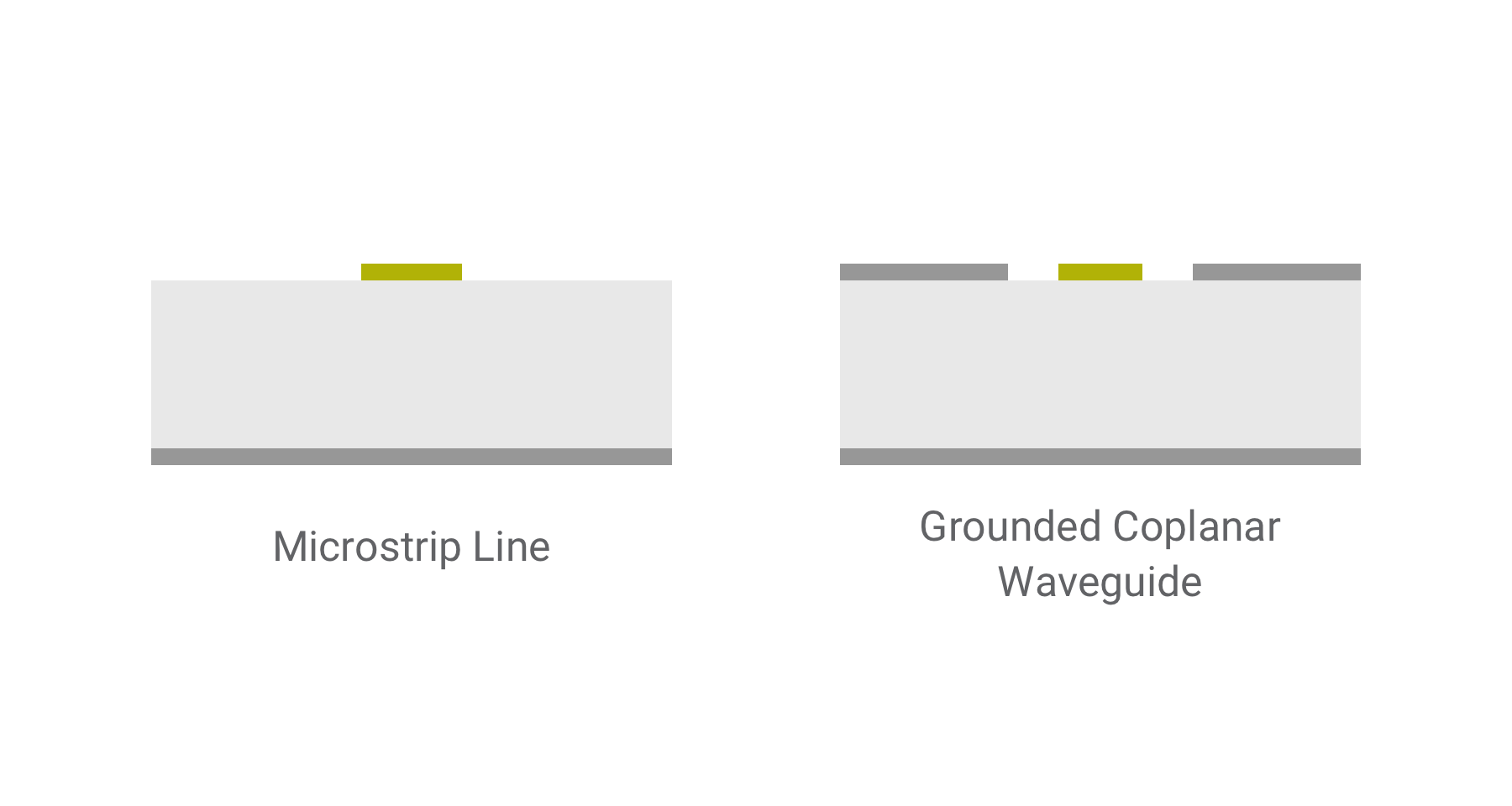
RF transmission lines are the traces that carry radio frequency energy to and from the antenna to the radio. There are many different types of transmission line used, however, there are two in particular that provide superior performance within embedded and compact applications. Microstrip transmission lines, a popular choice, are integrated on the top layer of a PCB, with a grounded layer beneath the dielectric. One of the major issues with this though is that these lines are not typically isolated enough, and in noisy environments, this can lead to losses and increased reflection coefficients.
Instead, the best practice for an embedded antenna is to design a grounded coplanar waveguide transmission line. When designing these, it’s important to note that the dimensions will determine the lines characteristic impedance.
Transmission lines carry radio frequency energy to and from the antenna to the radio. Ensuring that losses are minimised from the antenna to wireless modules is incredibly important.
Impedance matching and matching networks
Return loss is one of the most prevalent issues that come with the use of embedded antennas. The objects surrounding an antenna will interact with radiated electromagnetic fields. The greater the interference, the more likely that the transmission line will produce return losses, measured in the form of VSWR – the voltage standing wave ratio. A lower VSWR indicates that there are fewer losses.
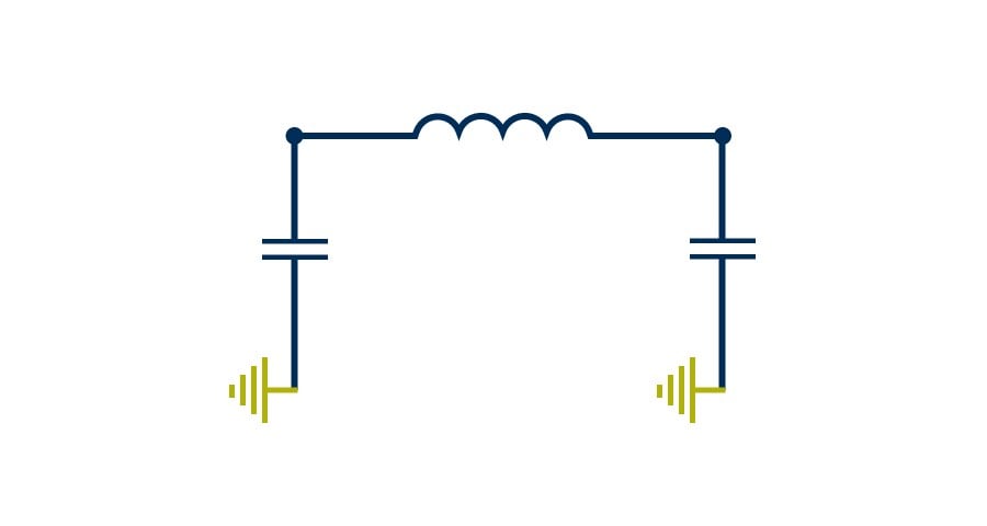
Matching networks help produce a characteristic impedance of as close to 50 ohms as possible. One simple solution for a matching network is to use a pi circuit, consisting of 3 or 5 (in the case of cellular and LTE applications) components.
Ground plane dimensions and clearance
Embedded antennas use ground planes on the host PCB in order to radiate effectively. The ground plane constitutes half of the antenna, so respecting the recommendations provided in data sheets is essential in any effort to achieve good levels of performance. In applications that require network certification, following the guidelines in datasheets is critical.
Clearance is another factor. Most antennas perform best on the corner of a circuit board, as this effectively means there are 5 directions where the antenna can operate as if it were in free space.
Vias – the holes that ‘knit’ together layers of a circuit board – have become increasingly important for improving performance in recent times. As more designs incorporate multi-layer circuit boards, often with more than two layers, reducing the effects of unintended ground beginning to resonate is critical. Running these vias at short intervals along the antenna feed line, the antenna and surrounding any other RF circuitry prevents these additional grounds from resonating and effectively becoming unintended transmission lines.
Optimise the board design
As new products launch in ever more adventurous applications, the performance of antennas in these scenarios is becoming a big challenge. Unfortunately, antennas play by a different set of rules to other digital components: the laws of physics. Without an optimised environment that enables them to function effectively, many designs could fail to make any commercial impact.
Antenova’s antennas are designed for integration, built to occupy tiny footprints in a low profile on a device’s PCB. When selecting an antenna, be sure to review the antenna’s full data sheet to understand the parts full requirements to operate efficiently. If you are at the stage where you are selecting the best antenna to integrate, feel free to post your question our forum to get advice from Antenova engineers and our global community.


.jpg?width=475&name=chris-barbalis-05902e-ZscE-unsplash%20(1).jpg)