How to integrate an FPC antenna for performance
Flexible printed circuit board (FPC) antennas offer designers a unique combination of performance, ease of integration, and flexibility. They deliver each of these benefits without the same real estate requirements and ground plane space that a surface-mounted device (SMD) antenna would need. This list of benefits and features bode well for a mixture of projects: especially for those where PCB real estate is at a premium or for a first-generation device where production volumes are going to be smaller.
Getting to know: FPC antennas
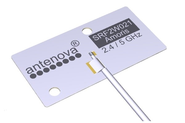
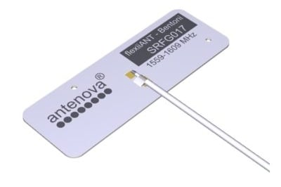
FPC antennas consist of an antenna on a flexible circuit, which connects to the host PCB via a coaxial cable (and connector). The circuit itself is highly flexible, with one side covered in adhesive, allowing it to be stuck down onto a product housing or away from the host PCB. They can even be bent around objects, which creates unique opportunities to integrate these antennas on a rigid design.
Most FPCs available on the market consist of a polyimide flexible PCB with a trace printed on the substrate, which can facilitate a range of antenna topologies, as designed for the application.
Recent innovations in flexible circuit technologies have enabled manufacturers to create solutions to overcome the increasing functionality required by Internet of Things devices, all while meeting miniaturisation requirements.
How to effectively integrate an FPC for maximum performance
FPC antennas offer designers a far easier integration solution than any other type of embedded antenna solution. However, there remains some key integration steps that are necessary to ensure the FPC antenna can perform well, radiate effectively and operate with high levels of efficiency. Particularly in small, compact devices, ensuring the antenna is integrated following these best practices will stand your device in the best position to perform well and meet certification requirements (if necessary).
The role of the coaxial cable
One of the most important factors in the integration of an FPC antenna is the placement and length of the coaxial cable, which is effectively a transmission line. For SMD antennas, optimising the transmission line is an integral part of the antenna system, and a poor transmission line design can impede antenna performance by as much as 50%. However, as FPC antennas typically come with an off-the-shelf cable, it’s easy to make the assumption that this cable is already optimised for performance. Yet there remains some vital steps to follow:
- Avoid bending the coaxial cable by more than 30 degrees. If it is necessary to integrate the antenna, the antenna will likely require tuning – Antenova customers can contact their local sales representative for custom antenna tuning services.
- Avoid overlapping coaxial cables with transmission lines, other coaxial cables and keep the cable away from antennas. In compact designs, it is common that cables will need to come into close contact with other RF circuitry or components, this should be avoided where possible to minimise performance impediment.
- Be aware that longer coaxial cables, especially those longer than 150mm, may suffer from cable loss – just as a longer transmission line would perform.
- Keep coaxial cables away from emitting components.
- Avoid looping the coaxial cable, as this will likely result in magnetic fields that will interact with the magnetic field of the antenna – causing it to shift frequency or, at its worst, render the antenna unable to function.
Orientation
The ideal orientation of the FPC will vary based on the design and shape of the device, product housing and the distance between the host PCB and the antenna.
As FPCs radiate in six spatial directions, the majority of these need to be free of obstructions in order to radiate effectively. To do this, you can mount the FPC vertically, coplanar to the PCB or on the same plane as the PCB. In each of these three orientations, you need to be aware of the minimum distance required between the antenna and the host PCB, which will be defined in the corresponding data sheet. Likewise, there will be information on the minimum required clearance from other components.
The orientation of the antenna will not impact performance too much, so long as the antenna’s radiation is not impeded by the host PCB or metal components – including metal materials which may be on the product housing. In these instances, an isolated, external-mount antenna may be more appropriate.
Connectors, cable length and cable placement
To provide even greater flexibility, the connectors on the coaxial cable, length of the cable and the placement of the cable on the FPC can be customised, subject to order volumes. Changing these can enable even greater opportunities to place an FPC antenna, especially where there are fewer potential locations to affix the FPC antenna. To learn more about the possibilities to customise Antenova’s flexiiANT FPC antennas, get in touch with your local representative from Antenova for more information.
Which FPC is right for you?
With a great combination of integration ease, integration flexibility and high levels of performance, FPC antennas are a great choice for many compact devices. But even between these types of antennas, there is plenty of choice, giving you the opportunity to find the perfect fit for your project.
Antenova’s flexiiANT product family consists of 11 high performance flexible circuit antennas, each created for high performance in the smallest form. They are available for ISM, GPS/GNSS, Cellular and WiFi/BT applications, in a range of different cable lengths. They have a wide range of benefits, including:
- No ground plane required.
- Less expensive than LDS antenna solutions.
- Easier, quicker integration.
- Higher levels of performance.
- Flexible placement options.


