Finding the best spot to place an antenna on a printed circuit board is undoubtedly an important decision. More than any other component, the placement decision for an antenna can enhance and equally detract from performance.
Even the most advanced, high-quality antennas available on the market will only thrive if their operating conditions are right. Everything from other antennas to the enclosure materials and even users can prevent signals from emanating from a device.
To ensure every device benefits from the best performance an antenna can possibly offer, here are the most important recommendations to follow when placing an antenna.
Use the datasheet as a reference document
Datasheets are incredibly useful resources for designers. However, they are very commonly misused. Many make the mistake of using a datasheet as a basis for technical comparison: using the performance parameters stated to compare between antennas. Yet the best choice of antenna isn't the one that performs best in free space, but the one that fits nicely within your design once the design-in guidelines are followed.
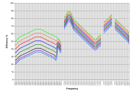
As antenna performance is governed by the physics involved in transmitting electromagnetic signals, the datasheet performance values really should only be used as a guideline. Achieving the performance values stipulated in a datasheet requires a highly optimised RF environment–virtually copying and pasting the recommended reference design. This, of course, is not always possible.
The reference design should be followed as much as possible once you have chosen an antenna, as it's these guidelines that enable the physics necessary for efficiency wireless performance.
Find the right place on the board
Most antennas perform best when placed on the corner of a PCB. This allows the antenna to have clearance in up to 5 different directions, except the direction where the feed connection is. This allows the antenna to drive currents in one direction. It’s also likely to be an area with the weakest concentration of other components and other potentially lossy materials.
Some antennas, such as Inversa and Integra, can work in tandem on multiple corners of a product's PCB to achieve a wireless MIMO system, necessary for 'true' 4G and LTE.
Ensure the antenna is not covered by a metallic enclosure
Metal-based materials act as a shield for antenna signals and block them from leaving a device, cutting lines of communication almost entirely. As such, no matter where an antenna sits within the PCB, it must not be completely covered by a metallic enclosure. This includes if the device’s casing has metallic properties. Similarly, no metal should be allowed in the antenna’s near-field.
Respect the keep-out area
Speaking of an antenna near-field, no components should be fitted within its keep-out area. The size and range of the keep-out area will change from antenna-to-antenna, but in all cases, no component, planes, mounting screws or traces should be placed within, on any layer of the PCB.
Plan for a matching network
As mentioned, a lot of factors within a PCB can affect an antenna’s performance – from ground variation to other components. To mitigate this a matching network will likely be required in order to retune the antenna. A pi matching network is often the best solution as it only uses a few components to correctly match an antenna to its source impedance. Antenova has produced a guide on the matching process, including how to achieve a pi matching circuit, which you can download for free here.
Place key components close to one another
Placing the antenna, impedance matching network and radio output close together will lessen any signal losses. Similarly, when using a matching network, ensure that trace length from the antenna is compliant with either the manufacturer datasheet or reference design.
Be wary of plastic
Plastic has a higher dielectric constant than air. When an antenna is close to plastic, it registers a higher constant, increasing the electrical length of the antenna trace and reducing the resonant frequency. This will drastically affect the signal and performance of an antenna, and so as a rule, never place the antenna close to any plastic that may exist within a design.
Antennas for challenging designs
Every design produces a unique set of challenges when integrating an antenna. It’s for this reason properly planning for an antenna, and anticipating some of the requirements they have is integral for achieving sufficient levels of performance.
Antenova’s range of antennas are all designed for integration, by the very same engineers that provide support for our customer’s. This means they’re not only among the easiest to integrate on the market, but they’re made to overcome the challenges engineers are facing today. Have a browse through our range of easy to integrate antennas or download our top integration tips if you have a solution in mind.