When designing products for 4G or 5G, choosing an antenna for your device is one of the most critical aspects of the design process. Not all applications require the high bandwidth provided by 5G – in many cases, 4G is sufficient for the majority of IoT applications. This guide will help you to understand the information usually found on an antenna datasheet and help you to pick out the key data for your project.
Datasheets for antennas typically contain a lot of information. An understanding of how antennas work is essential to deciphering the information provided. This will allow you to determine whether the antenna will be suitable for your product or application.
Physical and Electrical Parameters
The product datasheet for an antenna will detail the physical dimensions of the component. These are essential for use in devices with limited space, for applications such as the Internet of Things (IoT), where engineers are striving to create ever-smaller devices.
Next on the datasheet are the frequency bands for which the antenna has been assessed. The antenna will have been designed for certain bands, with specific values for a range of antenna parameters:
- Peak/Average gain
- Efficiency
- Return loss
- Voltage Standing Wave Ratio (VSWR)
Not only are these parameters essential to the functioning and user experience of the end device, but they are key characteristics that are required for device certification. If your device will be operating on cellular data networks, network carriers require device certification before they allow the device. This is necessary for the device to be launched on the commercial market.
Efficiency is a critical metric to consider. An antenna with a lower efficiency will result in worse performance, as RF energy will be lost as either heat, or reflected energy to the source.
Ground plane length vs. efficiency – what is stipulated in the datasheet?
When evaluating antennas, you should consider the efficiency values in the datasheet, but also consider the ground plane length that has been used to derive those values.
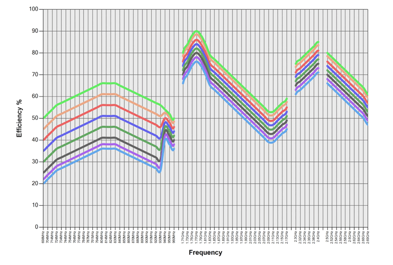
.png?width=800&name=efficiency-gndplane%20(1).png) Figure 1. Efficiency plot for typical cellular antenna.
Figure 1. Efficiency plot for typical cellular antenna.
The coloured lines show the different lengths of ground plane used, the chart shows that a longer, larger ground plane, means that the antenna performs with higher levels of efficiency. Conversely, a smaller ground plane results in a less efficient antenna. At lower frequencies, efficiency is impacted to a higher degree by ground plane length.
 Figure 2. Key for Figure 1 – colour notations for each ground plane length.
When selecting an antenna for your product, it is worth comparing datasheets to ensure that the antenna meets all your requirements before you start. However, there are many real-world factors that datasheet information cannot account for.
Datasheet information is generated using an antenna evaluation kit (EVK). So the information in the datasheet is based on a specific set of conditions. Changing these conditions (such as PCB length, thickness, and proximity of other components) will affect the performance of the antenna.
During the development process, Antenova measures antenna efficiency with different ground plane lengths. This is to optimise the efficiency for each ground plane length – so that at lower frequencies, the antenna retains high efficiency levels. Our antennas are developed and tested for small devices, down to a PCB length of just 80 mm, as these often pose the greatest challenge in terms of product design. Extensive testing and antenna development guarantees consistent performance across a wide range of devices and allows seamless integration into the end-product.
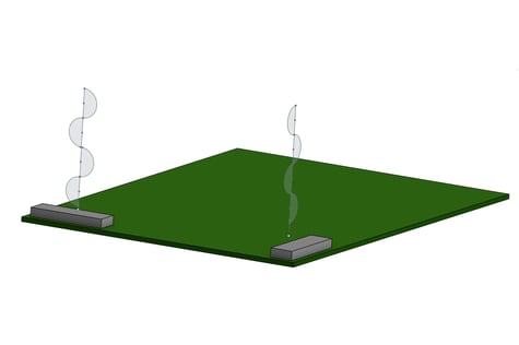
This is the part of the datasheet that people often gloss over because it looks complicated. However, these 3D radiation patterns, and gain plots are essential to understanding the effectiveness of an antenna. This plot shows how the antenna radiates energy into its surroundings. A perfect antenna would radiate energy in a sphere, but in reality, we see a variety of different shapes. For a standard dipole antenna, the shape of the radiation pattern is more like a doughnut. For a dipole antenna mounted on a Printed Circuit Board (PCB), the PCB acts as a ground plane. We mount our antennas at the end, rather than the centre, so energy is radiated out spherically.
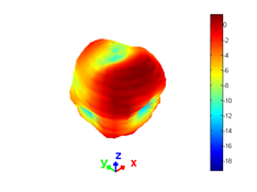
Figure 3. Radiation pattern.
The colours indicate the strength of signals. The red and orange colouring shows where there are stronger signals, whereas green and blue indicates where signals are weaker. Note that the shape resembles a sphere with a hole going through from the bottom right-hand side, similar to a doughnut.
The visual representations of radiation patterns detailed in the data sheet are based on experimental values measured using an antenna evaluation kit (EVK) in an anechoic chamber. Testing is carried out at different frequency bands, which is why we often see a few pages of graphs and 3D images in the datasheet.
Antenna Integration
Finally, the product specification also gives information on how to physically integrate the antenna into your device. Correct antenna placement can be the difference between passing or failing network certification tests and meeting other performance criteria. Antenna manufacturers will always recommend placing the antenna away from other components or metal objects.
The coaxial cable of a flexible printed circuit (FPC) antenna is the equivalent of a waveguide in an FR4 antenna. When comparing between datasheets, keep in mind that FR4 antennas utilise coplanar waveguides (CPW), surrounded by a ground, which needs to be optimally designed for maximum performance. To see how to do this, Antenova has developed a tool that calculates the optimum dimensions of this waveguide, access the tool here.
This section of the datasheet will also make recommendations, relating to connecting coaxial cables and other wiring. It will also give information on how to mount the antenna within your device and any other connections that you will require. To ensure the optimum FR4 antenna placement on a PCB, we’ve created a tool that recommends the placement for best antenna performance.