
Miniaturisation is hardly a new trend, but sleeker, more compact devices are creating environments where it is harder for an embedded antenna to perform well. On devices with tiny PCBs, there is an inverse relationship between available ground plane space and wireless performance and efficiency. Where a device requires carrier certification, the entire project revolves around successfully passing carrier tests – where it’s estimated that more than half of all devices fail on the first attempt.
The challenge compounds at sub-1GHz frequencies, where ground plane length requirements exceed 10cm. In designs with less ground plane length, the efficiency for the antenna will significantly drop. The physical layout of a host PCB is therefore critical to consider, many factors of which could be classified as mechanical considerations.
We recommend taking a decision on an antenna in the early stages of a project, where there are fewer restrictions that could impede the performance of an antenna. Taking this approach is important, as the relationship between physical design and antenna performance is intrinsically linked.
Mechanical considerations
Enclosure materials
In order for an embedded antenna to perform well, it needs an enclosure that allows RF energy to leave the device. The most common material that causes issues are metals, although composite materials can also interfere with the antenna’s radiation and efficiency.
Generally, materials such as ABS and other polycarbonate plastics allow antennas to radiate effectively, so opt for these if you can. Otherwise, you may want to consider creating a ‘window’ in your enclosure to allow RF transmission.
It is not only the material of the enclosure that can affect performance, however. The gap between the housing and an antenna (which is typically best placed on the outside edge of a host PCB) should be greater than 3mm.
Circuit board size
Smaller devices equal smaller circuit boards. More compact circuit boards are generally more complex, too, especially as more and more features are packed into modern devices. Not only does this mean that circuit boards are typically smaller, but there’s even less room dedicated to an antenna and associated RF circuitry/components.
Our 2018 white paper explored the trade-off between circuit board size and antenna performance. It reviewed emerging wireless technologies such as NB-IoT (and other long-range, low power enabling technologies), concluding that while these devices needed to be small, the physical requirements of the antenna necessitated 10cm or greater of ground plane length.
For devices that require certification, finding sufficient space to operate an antenna is essential. Especially in markets such as North America, the performance benchmarks can be difficult to reach.
Diversity, crosstalk and isolation
On smaller circuit boards, there is less space to physically isolate multiple antennas, even if they are operating at different frequencies. For example, in automotive applications (such as an OBD tracker), it is important that the GNSS receiver operates with a cellular antenna nearby in a small package.
Where multiple antennas are in use on the single circuit board, data sheets are useful resources to find a set of antennas that can be placed on opposite sides of the circuit board.
There are also issues that occur from the location of nearby components. Parasitic coupling occurs when antennas crosstalk with other radiating signals. This can occur with wires, switches and many other components.
Design requirements
The design requirements of every device will differ somewhat. It’s not possible to have a single antenna design that covers all requirements. The intricacies of every device will mean the design-in and integration challenges in every project will differ.
What about drop-in solutions?
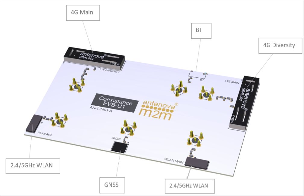
Antenna manufacturers frequently create reference designs with evaluation boards that demonstrate the optimum placement and keep-out areas to position the antenna free of components that could generate noise.
- Reference designs. Many antenna manufacturers create reference designs (such as this LTE blade solution or this OBD-II solution) that can be used to achieve high levels of performance with minimal customisation.
- Evaluation boards. Antenna manufacturers also create evaluation boards that can be a useful design reference for integrating an antenna with minimal intervention. Provided the space is available on the host PCB, this can be a good way to integrate a proven solution.
- Customised antennas. Some antenna manufacturers offer the opportunity to customise off-the-shelf antennas so that they can be successfully retrofitted within a device – minimum order quantities may apply – but this will enable you to access the expertise and resources you need to achieve the best performance within the completed design.
Selecting the right antenna
Approaching the antenna integration process early on in the design cycle is important. It will ensure you can integrate an antenna as seamlessly as possible, while meeting the design requirements to ensure it can perform well. This is especially important where certification is concerned: a device that fails to perform well may not be approved for a specific market.