The Internet of Things (IoT) has become unfathomably diverse. Devices are leveraging new technologies, solving new problems and are transforming markets. While they’ve become more diverse, they are still capable of delivering exceptional levels of wireless performance, despite the trickiness associated with wireless antenna integration.
Transmission lines are a key factor in determining wireless performance. These lines carry RF energy to and from an antenna. A poorly optimised transmission line can cause wireless performance to drop by as much as 50%. Given the fact that devices are shrinking and getting more compact, the importance of optimising a transmission line has never been greater.
Are GCPWs the best option for countering noise and reflections?
Transmission lines are critical to performance – especially in compact devices using embedded antennas. Compact devices tend to be noisier and therefore less conducive to wireless performance. In these scenarios, a type of transmission line called a grounded coplanar waveguide–or GCPW–is generally recommended.
The challenge becomes even greater when you take into consideration the number of devices using multiple antennas. In MIMO and multi-technology applications, the presence of multiple antennas and RF circuits adds to the challenge. For this reason, choosing a transmission line that offers versatility, design flexibility and better isolation tends to yield the best results – and that’s precisely what GCPWs can do.
GCPWs are configured in what’s known as a ground-signal-ground configuration on the top layer. Additionally, the signal is isolated further with an additional ground plane beneath the signal.
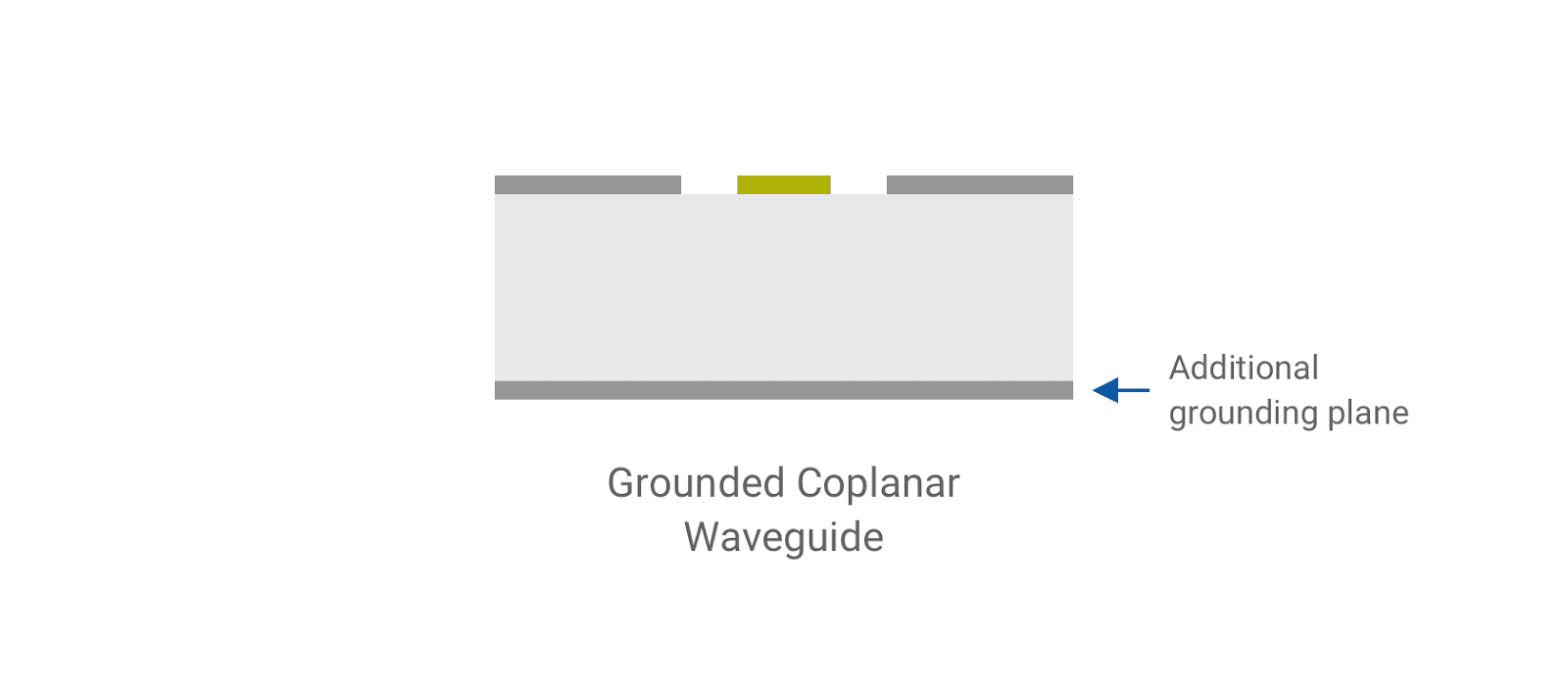
Figure 1. Grounded coplanar waveguide cross-section
This configuration lends itself well for high frequency applications. The G-S-G configuration offers good isolation from interference and generally minimises radiation losses, when designed optimally.
Another advantage of this arrangement is the flexibility it offers designers. The dimensions and physical layout of a transmission line will define the characteristic impedance of the transmission line. With no fewer than four dimensions on offer to customise, designers are afforded plenty of options when it comes to accurately matching for impedance.
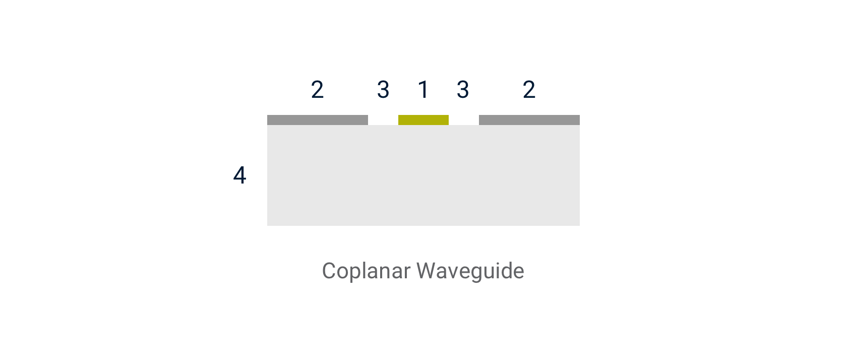
Figure 2. The four components of the coplanar waveguide
There are four different parts of a CPW, these are:
- The conductive strip.
- Surrounding ground planes.
- Isolating gaps.
- Dielectric substrate layer.
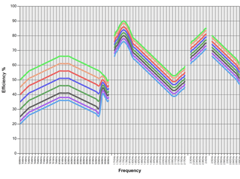
There are even calculators available to allow you to quickly ascertain the optimal dimensions for a traceline based on the dielectric constant of the PCB substrate. Antenova has created a transmission line calculator that outputs a dynamic chart that plots the necessary dimensions to achieve impedance matches for 55Ω, 45Ω, and 50Ω.
Design considerations
GCPWs require consistent and careful design to function as intended. As with other types of transmission line, their dimensions and length are key. The longer a transmission line is, the more interference signals will be subjected to as they travel along the line. It is important, therefore, to keep the length of the line to no more than 10% of wavelength, especially when designing for high-frequency applications.
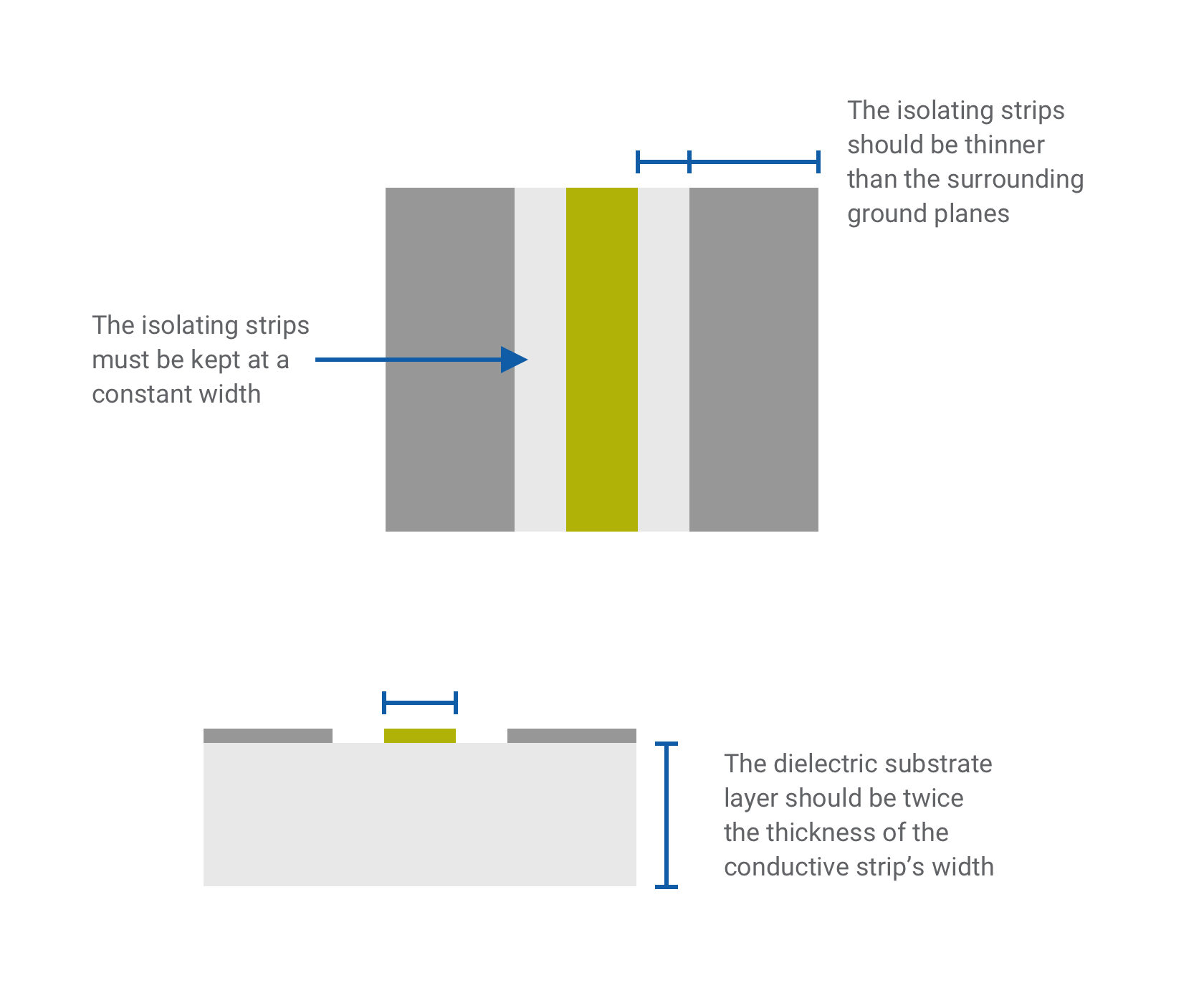
It is essential when using coplanar waveguides that the width of the isolating gaps is kept consistent along the whole length of the line. The gaps must also be slimmer than the surrounding ground planes to avoid diminished performance. The width of these gaps can alter the characteristic impedance, so maintaining the uniformity of these lines prevents impedance mismatching. Lastly, the dielectric substrate layer should be twice the thickness of the conductive strip’s width.
GCPW Advantages
- The isolated conductor reduces reflections.
- Performs well at high frequencies.
- Impedance can be tuned by adjusting the width of the isolating gaps and ground planes.
- Compatible with a range of high-frequency technologies, including 5G's new radio.
- The material chosen for the PCB has less effect on loss.
GCPW Considerations
- Small design mistakes can lead to substantial loss of effectiveness.
- If the PCB uses thick copper plating, the CPW will be subject to an increased electromagnetic field and thus suffer from interference.
- More expensive to manufacture than alternative transmission line types.
- More prone to human error in installation than alternatives.
- Some software packages do not support their design out-of-the-box.
When should you use a grounded coplanar waveguide?
GCPWs are a good choice when interference is likely, when the cost is less of a priority, or in ultra-compact, miniaturised designs. While they are more expensive than alternatives such as the microstrip line, their performance in most situations is far stronger. For larger applications, the coaxial cable might be a better choice due to its cost-effectiveness, ease of use and ability to avoid interference. However, the GCPW still comes out on top for small, compact systems where coaxial cables are unable to be used.