Unlike any other component, wireless antennas are completely unique. Their performance is wholly a product of their operating environment. Whilst other electronic components can be integrated successfully through calculation, wireless antenna may pose some surprising issues when you attempt to integrate them.
This means that the stack up on your PCB design could actually cause antenna inefficiencies and actually cause a product not to work. When you’re working to a budget and operating to strict timelines, this could potentially prevent a product from launch. This places a huge amount of pressure on development teams.
The importance of trace lines
Trace lines (A.K.A coaxial cables or transmission lines) play an important role in determining the overall level of antenna performance. Improperly designing these on your PCB could slash your performance metrics in half, even render a product unable to function.
The makeup of the electromagnetic fields that are used by antenna mean that these lines should yield a particularly high impedance. Almost every wireless antenna operates most effectively at 50 ohms. When these lines aren’t properly ‘matched’ to the source impedance, then this will increase the reflection coefficient of an antenna.
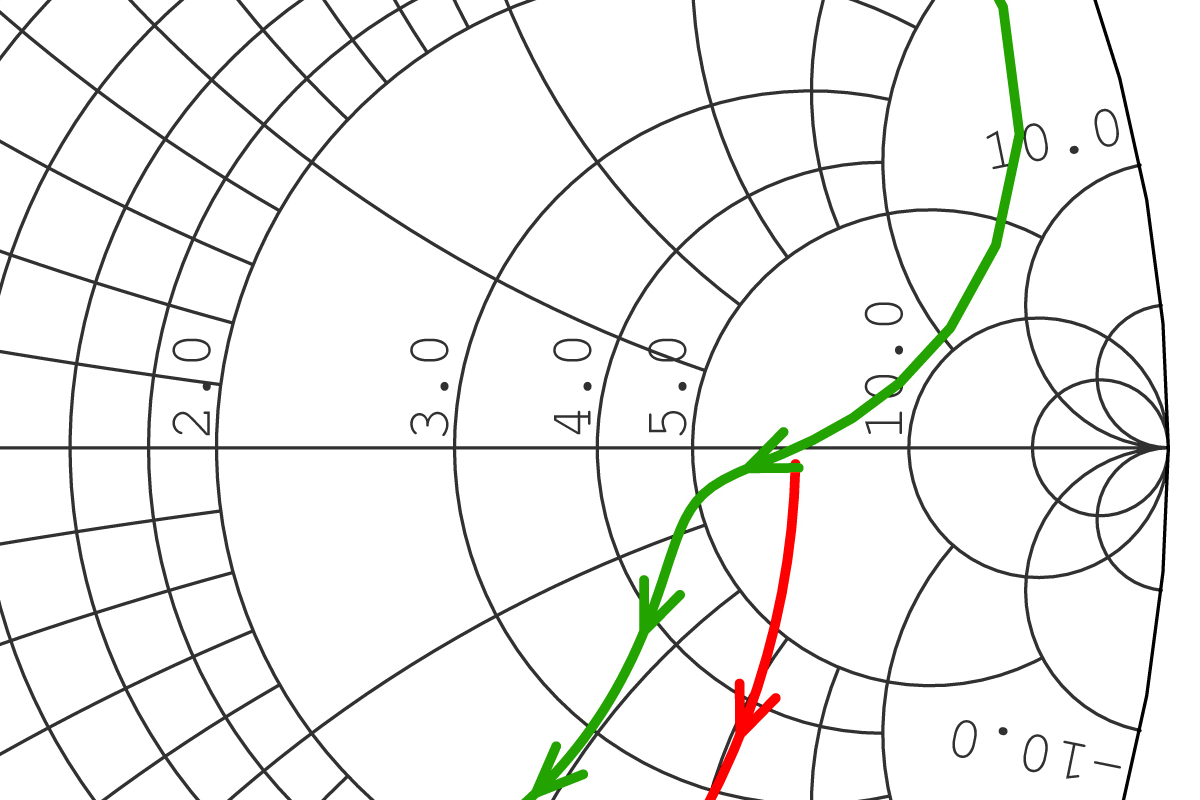
Impedance mismatches
Matching involves aligning the impedance of the RF circuitry and the antenna chip to 50 ohms. If these are not correctly matched, then an antenna may be susceptible to several devastating consequences:
Frequency shifting
A mismatched antenna will ‘shift’ away from the operating frequency due to irregularly placed components and even the enclosure of a device. In the worst cases, this can prevent a device from functioning correctly - an absolute nightmare if this is discovered after a device has been commissioned for manufacture.
High reflection coefficients
A high Voltage Standing Wave Ratio (VSWR) essentially means that RF energy is not reaching the antenna. This can mean that transmissions are reflected back onto a trace line and not actually transmitted.
Environmental impacts
Devices aren’t always operating in free space. Handheld, wearable and devices that are situated in particularly stressful environments can be mismatched by environmental factors. Even a correctly matched antenna in free space can be mismatched by the operating environment of a device.
Optimally tuning an antenna
Design decisions made at every point of the development cycle will impact the tuning of an antenna. It’s therefore essential that trace line impedance, VSWR and in-situ performance is reviewed throughout the process. It’s also important that your trace lines are correctly suited to achieving a close match.
The dimensions and physical form of your trace lines will impact the matching of an antenna. We recommend you use grounded coplanar waveguides for most embedded antenna, as they provide the most flexibility and control over impedance mismatching. This will ensure the highest levels of performance. To calculate the optimum trace line dimensions for your antenna, get the free Antenova Trace Line calculator.
To learn more about the matching process, the basic principles and methodologies to help you achieve optimum performance in your device, get the Ultimate Guide to Antenna Matching.